
AutoCAD P & ID
About Course
Course Description:
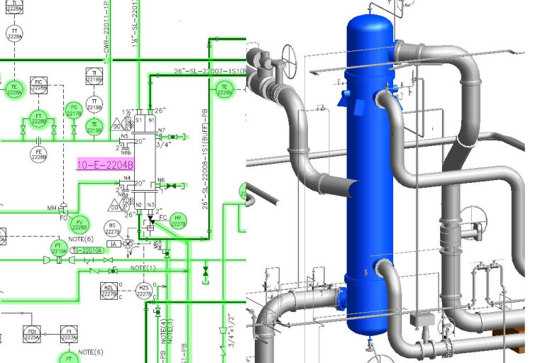
P & ID is a schematic diagram showing piping, equipment and instrumentation connections within process units in oil refineries, petrochemical and chemical plants, natural gas processing plants, power plants, water treatment and other similar plants.
It is a functional relationship diagram of Piping, Instrumentation and System Equipment components in the process industry which shows the piping of the process flow together with the installed equipment and instrumentation. P&ID shows all of piping and its components including the physical sequence of branches, reducers, values, equipment, instrumentation and control interlocks.
Piping is used in commercial and industrial applications for fluid handling were the wish is to transmit a fluid from one point to another. You need to look no further than your home come across a variety of piping system including water, sewage and possibly gas.
The name piping covers a broad-spectrum including pipe, fitting, valves and a piping. A draftsperson or CAD operator must be familiar with equipment, instrumentation and related disciplines in addition to the any facets of plant design.
The Piping and Instrumentation diagram is the road map for completing piping layout /arrangement drawings. The Piping and Instrumentation Diagram (P&ID) is developed from the Process Flow Diagram (PFD) and is a schematic drawing representing the process equipment, showing nozzles, all pipes and in-line fitting (valves, tees, reducers, strainers, sight glasses, drains, vents, sample point, Control valves etc.) Instruments and control loops (but not instrument piping), and some electrical data such as tracing and motor drives.
In a small plant all process and utility piping would be included in the P&ID. The piping and instrumentation diagram (P&ID), also known as mechanical flow diagram (MFD), provides information needed by engineers to begin planning for the construction of the plants.
Course Highlights
This course will:
- Provide a clear and concise illustration of all equipment, pipes, valves, instruments, sensors, etc. so that anyone involved has a solid understanding of the process.
- Provide information to assist in analyzing process hazards, safeguards and potential faults so that all kinds of errors (design, human/operation, etc.) are minimized, ideally eliminated.
- Support development of operating and maintenance procedures.
- Serve as an as-built records of the process so that changes can be planned safely and effectively using Management of Change (MOC).
Course Benefits
This course will:
- Allow participants to learn many of the essential features of AutoCAD P & ID, including how to create P&IDs by placing equipment, connecting equipment with pipelines, and adding valves, reducers and pipe fitting.
- Act as the definition of the process from which all engineering, fabrication, construction and operation are based. Serve as reference for Process Safety Information (PSI) in Process Safety Management (PSM).Serve as working templates for real plant modeling
- Provide a library of symbols that you can access from a tool palette and place in your drawing to streamline your efforts. Enable you to work exclusively in a project environment, so that your drafting is consistent with others working on the same project.
- Enable you to create reports for a single drawing or an entire project.
- Enable us to have an enhanced understanding of the Oil & Gas processes
- Enable us to have an Improved Design and Engineering
- Allows us to have an Effective Documentation and Standardization
- Allows us to have Facilitated Maintenance and Troubleshooting exercises.
- Allow us to maintain Compliance and Regulatory Requirements